- 您现在的位置:买卖IC网 > Sheet目录3872 > PIC16F627A-I/ML (Microchip Technology)IC MCU FLASH 1KX14 EEPROM 28QFN
PIC16F627A/628A/648A
DS40044G-page 104
2009 Microchip Technology Inc.
14.4.5
TIME OUT SEQUENCE
On power-up, the time out sequence is as follows: First
PWRT time-out is invoked after POR has expired. Then
OST is activated. The total time out will vary based on
oscillator configuration and PWRTE bit Status. For
example, in RC mode with PWRTE bit set (PWRT
disabled), there will be no time out at all. Figure 14-8,
Figure 14-11 and Figure 14-12 depict time out
sequences.
Since the time outs occur from the POR pulse, if MCLR
is kept low long enough, the time outs will expire. Then
bringing MCLR high will begin execution immediately
(see Figure 14-11). This is useful for testing purposes
or to synchronize more than one PIC16F627A/628A/
648A device operating in parallel.
Table 14-6 shows the Reset conditions for some
special registers, while Table 14-7 shows the Reset
conditions for all the registers.
14.4.6
POWER CONTROL (PCON) STATUS
REGISTER
The PCON/Status register, PCON (address 8Eh), has
two bits.
Bit 0 is BOR (Brown-out Reset). BOR is unknown on
Power-on Reset. It must then be set by the user and
checked on subsequent Resets to see if BOR = 0
indicating that a brown-out has occurred. The BOR
Status bit is a “don’t care” and is not necessarily
predictable if the brown-out circuit is disabled (by
setting BOREN bit = 0 in the Configuration Word).
Bit 1 is POR (Power-on Reset). It is a ‘0’ on Power-on
Reset and unaffected otherwise. The user must write a
‘1’ to this bit following a Power-on Reset. On a
subsequent Reset if POR is ‘0’, it will indicate that a
Power-on Reset must have occurred (VDD may have
gone too low).
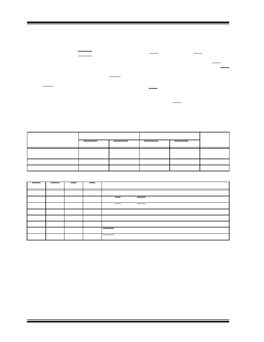
TABLE 14-3:
TIME OUT IN VARIOUS SITUATIONS
TABLE 14-4:
STATUS/PCON BITS AND THEIR SIGNIFICANCE
Oscillator Configuration
Power-up Timer
Brown-out Reset
Wake-up from
Sleep
PWRTE = 0
PWRTE = 1
PWRTE = 0
PWRTE = 1
XT, HS, LP
72 ms +
1024TOSC
72 ms +
1024TOSC
RC, EC
72 ms
—
72 ms
—
INTOSC
72 ms
—
72 ms
—
6
μs
POR
BOR
TO
PD
Condition
0X11
Power-on Reset
0X0X
Illegal, TO is set on POR
0XX0
Illegal, PD is set on POR
10XX
Brown-out Reset
110u
WDT Reset
1100
WDT Wake-up
11uu
MCLR Reset during normal operation
1110
MCLR Reset during Sleep
Legend:
u
= unchanged, x = unknown
发布紧急采购,3分钟左右您将得到回复。
相关PDF资料
PIC24F08KL401-I/P
IC MCU 16BIT 8KB FLASH 20-PDIP
PIC16LF727-I/P
IC PIC MCU FLASH 8K 1.8V 40-DIP
PIC12C672-10/SM
IC MCU OTP 2KX14 A/D 8-SOIJ
PIC16LF628A-I/P
IC MCU FLASH 2KX14 EEPROM 18DIP
PIC18LF14K50-I/MQ
IC PIC MCU FLASH 768KX16 20-QFN
PIC16F1934-I/P
IC PIC MCU FLASH 256KX7 40-PDIP
PIC16CE623-04/P
IC MCU OTP 512X14 EE COMP 18DIP
PIC16F1939-I/PT
IC MCU 8BIT FLASH 44TQFP
相关代理商/技术参数
PIC16F627A-I/ML
制造商:Microchip Technology Inc 功能描述:8BIT FLASH MCU SMD 16F627 QFN-28
PIC16F627A-I/P
功能描述:8位微控制器 -MCU 1.75KB 224 RAM 16I/O Ind Temp PDIP18 RoHS:否 制造商:Silicon Labs 核心:8051 处理器系列:C8051F39x 数据总线宽度:8 bit 最大时钟频率:50 MHz 程序存储器大小:16 KB 数据 RAM 大小:1 KB 片上 ADC:Yes 工作电源电压:1.8 V to 3.6 V 工作温度范围:- 40 C to + 105 C 封装 / 箱体:QFN-20 安装风格:SMD/SMT
PIC16F627A-I/P
制造商:Microchip Technology Inc 功能描述:IC 8BIT FLASH MCU 16F627 DIP18
PIC16F627A-I/SO
功能描述:8位微控制器 -MCU 1.75KB 224 RAM 16I/O Ind Temp SOIC18 RoHS:否 制造商:Silicon Labs 核心:8051 处理器系列:C8051F39x 数据总线宽度:8 bit 最大时钟频率:50 MHz 程序存储器大小:16 KB 数据 RAM 大小:1 KB 片上 ADC:Yes 工作电源电压:1.8 V to 3.6 V 工作温度范围:- 40 C to + 105 C 封装 / 箱体:QFN-20 安装风格:SMD/SMT
PIC16F627A-I/SO
制造商:Microchip Technology Inc 功能描述:8BIT FLASH MCU SMD 16F627 SOIC18
PIC16F627A-I/SS
功能描述:8位微控制器 -MCU 1.75KB 224 RAM 16I/O Ind Temp SSOP20 RoHS:否 制造商:Silicon Labs 核心:8051 处理器系列:C8051F39x 数据总线宽度:8 bit 最大时钟频率:50 MHz 程序存储器大小:16 KB 数据 RAM 大小:1 KB 片上 ADC:Yes 工作电源电压:1.8 V to 3.6 V 工作温度范围:- 40 C to + 105 C 封装 / 箱体:QFN-20 安装风格:SMD/SMT
PIC16F627A-I/SS
制造商:Microchip Technology Inc 功能描述:8BIT FLASH MCU SMD 16F627 SSOP20
PIC16F627AT-E/SO
功能描述:8位微控制器 -MCU 1.75KB 224 RAM 16I/O Ext Temp SOIC18 RoHS:否 制造商:Silicon Labs 核心:8051 处理器系列:C8051F39x 数据总线宽度:8 bit 最大时钟频率:50 MHz 程序存储器大小:16 KB 数据 RAM 大小:1 KB 片上 ADC:Yes 工作电源电压:1.8 V to 3.6 V 工作温度范围:- 40 C to + 105 C 封装 / 箱体:QFN-20 安装风格:SMD/SMT